Overview
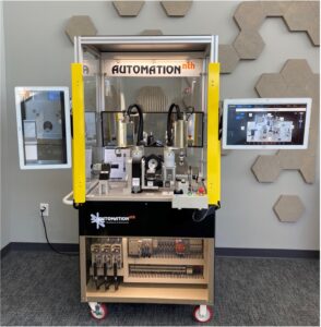
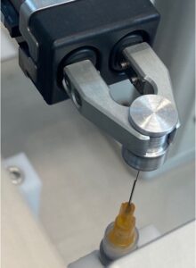
This precision controlled movement allows us to demonstrate the assembly of two common medical subcomponents, a stylet and cannula.
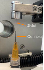
The stylet is a flexible metal wire that is 0.010” (.254 mm) in diameter. The cannula is a hollow, very narrow tube with an Inner Diameter (ID) of 0.013”(0.3302mm). Cannulas are often used to house a needle or stylet for IVs and syringes. In this demonstration, the cannula is threaded into a fixed syringe prior to stylet insertion.
Challenges
The machine was designed to demonstrate our ability to solve a number of complex challenges including:
- Precision: The wire insertion process requires a very high level of precision: ± 21 µm accuracy, angular tolerance of 1.5°, and robot movements with ± 5 µm accuracy.
- Quality: The stylet should not touch the inner wall of the cannula to prevent the stylet from being damaged.
- Variability: Stylets are all unique with variable wire bends, angles, and lengths and the machine needs to be flexible to handle the wide variety of parts.
The Solution
Automation NTH solved these challenges by utilizing a SCARA 4 axis robot along with 2 servos mounted on the tabletop to allow for independent motion.
This configuration allows the machine to tilt the syringe body holding the cannula in the Theta X and Theta Y directions to handle angle variability in the stylets.
Since every stylet is different, the machine utilizes vision to guide the robot into position to align the cannula with the stylet for insertion.
Process Overview
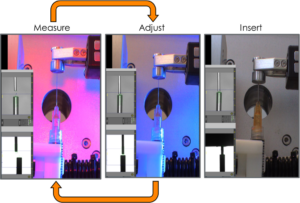
A robot picks a cannula from the nest and threads it into the syringe body to fix it into place. The other robot then picks a stylet from the nest and moves to an approach position to present the stylet to the cameras. Both cameras take a picture and measure offsets.
Then a feedback loop between the robot, camera, and servos is created.
- Measure the cameras take a picture and measure offsets.
- Adjust the robot moves the stylet based on the cameras measurement, and the servos tilt the cannula based on the cameras measurement.
- Loop until the stylet is lined up within ± 21 µm, then insert the stylet into the cannula.
Vision System
Camera and Lens Selection
Many factors are considered during selection of the camera and lens, including size, resolution, acquisition time, and ease of use.
We selected a Cognex 8000 series camera due to its ultra-compact size, up to 5MP Resolution, and very fast processing times.
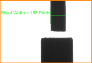
The width of the stylet is 163 pixels wide (.010” or .254 mm) from the camera’s view.
The size of each pixel is 1.8 microns. So, with a tolerance required of +- 21 microns we have at least 10 pixels of width from which to accurately measure.
Y-Axis Camera
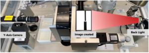
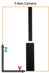
The Y-Axis camera is responsible for measuring Y and Z Distance and Theta Y angle of the stylet and cannula.
The image to the left shows the image captured from the camera. The image has a very high contrast due to the backlight, which allows the camera to easily identify and measure the stylet and cannula.
The X axis camera uses an approach and programming that is similar to the Y axis camera.
Using the Position data
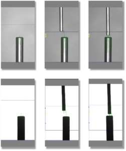
The offset angles of theta X and Y are sent to the servo to tilt the cannula.
The X, Y, and Z offsets are sent to the robot to move the stylet closer to the cannula.
The PLC will then trigger the cameras to measure again and the cycle repeats until the stylet and cannula are perfectly lined up, at which point the stylet is inserted into the cannula.
Summary
This Vision Guided Robotic Wire Insertion machine demonstrates Automation NTH’s ability to create innovative solutions for complex, high precision assembly applications. We invite you to see it in person either at a trade show or our headquarters in Nashville!

